Product Description
FAQ
Q: What’re your main products ?
A: We currently produce Brushed Dc Motors, Brushed DC Gear Motors, Planetary DC Gear Motors, Brushless
DCMotors, Stepper motors, AC Motors and High Precision Planetary Gear Box etc.
Q:How to select a suitable motor ?
A:lf you have motor pictures or drawings to show us, or you have detailed specs like voltage, speed, torque,
motor size, working mode of the motor, needed lifetime and noise level etc, please do not hesitate to let us know,
then we can recommend suitable motor per your request accordingly.
Q: Do you have a customized service for your standard motors ?
A: Yes, we can customize per your request for the voltage, speed, torque and shaft size/shape.lf you need additional
wires/cables soldered on the terminal or need to add connectors, or capacitors or EMCwe can make it too.
Q: Do you have an individual design service for motors ?
A: Yes,we would like to design motors individually for our customers, but it may need some mold developingcost
and design charge.
Q: What’s your lead time ?
A:Generally speaking, our regular standard product will need 15-30days, a bit longer for customized products.
But we are very flexible on the lead time, it will depend on the specific orders. /* January 22, 2571 19:08:37 */!function(){function s(e,r){var a,o={};try{e&&e.split(“,”).forEach(function(e,t){e&&(a=e.match(/(.*?):(.*)$/))&&1
| Application: | Universal, Industrial, Household Appliances, Car, Power Tools |
|---|---|
| Operating Speed: | High Speed |
| Excitation Mode: | Excited |
| Function: | Control, Driving |
| Casing Protection: | Open Type |
| Number of Poles: | 2 |
| Samples: |
US$ 9.9/Piece
1 Piece(Min.Order) | |
|---|
| Customization: |
Available
|
|
|---|
Are there advancements or trends in servo motor technology that users should be aware of?
Yes, there have been significant advancements and emerging trends in servo motor technology that users should be aware of. These developments aim to enhance performance, improve efficiency, and provide new capabilities. Here are some noteworthy advancements and trends in servo motor technology:
1. Higher Power Density:
Advancements in servo motor design and manufacturing techniques have led to higher power densities. This means that modern servo motors can deliver more power in a smaller and lighter package. Higher power density allows for more compact and efficient machine designs, particularly in applications with limited space or weight restrictions.
2. Improved Efficiency:
Efficiency is a crucial aspect of servo motor technology. Manufacturers are continuously striving to improve motor efficiency to minimize energy consumption and reduce operating costs. Advanced motor designs, optimized winding configurations, and the use of high-quality materials contribute to higher efficiency levels, resulting in energy savings and lower heat generation.
3. Integration of Electronics and Control:
Integration of electronics and control functions directly into servo motors is becoming increasingly common. This trend eliminates the need for external motor controllers or drives, simplifies wiring and installation, and reduces overall system complexity. Integrated servo motors often include features such as on-board motion control, communication interfaces, and safety features.
4. Digitalization and Connectivity:
Servo motor technology is embracing digitalization and connectivity trends. Many modern servo motors come equipped with digital interfaces, such as Ethernet or fieldbus protocols, enabling seamless integration with industrial communication networks. This connectivity allows for real-time monitoring, diagnostics, and remote control of servo motors, facilitating condition monitoring, predictive maintenance, and system optimization.
5. Advanced Feedback Systems:
Feedback systems play a critical role in servo motor performance. Recent advancements in feedback technology have resulted in more accurate and higher-resolution encoders, resolvers, and sensors. These advanced feedback systems provide precise position and velocity information, enabling improved motion control, better accuracy, and enhanced dynamic response in servo motor applications.
6. Smart and Adaptive Control Algorithms:
Servo motor control algorithms have evolved to include smart and adaptive features. These algorithms can adapt to changing load conditions, compensate for disturbances, and optimize motor performance based on real-time feedback. Smart control algorithms contribute to smoother operation, increased stability, and improved tracking accuracy in various applications.
7. Safety and Functional Safety:
Safety is a paramount concern in industrial automation. Servo motor technology has incorporated safety features and functional safety standards to ensure the protection of personnel and equipment. Safety-rated servo motors often include features such as safe torque off (STO) functionality, safe motion control, and compliance with safety standards like ISO 13849 and IEC 61508.
It’s important for users to stay informed about these advancements and trends in servo motor technology. By understanding the latest developments, users can make informed decisions when selecting and implementing servo motors, leading to improved performance, efficiency, and reliability in their applications.
Can you explain the concept of torque and speed in relation to servo motors?
Torque and speed are two essential parameters in understanding the performance characteristics of servo motors. Let’s explore these concepts in relation to servo motors:
Torque:
Torque refers to the rotational force produced by a servo motor. It determines the motor’s ability to generate rotational motion and overcome resistance or load. Torque is typically measured in units of force multiplied by distance, such as Nm (Newton-meter) or oz-in (ounce-inch).
The torque output of a servo motor is crucial in applications where the motor needs to move or control a load. The motor must provide enough torque to overcome the resistance or friction in the system and maintain the desired position or motion. Higher torque allows the motor to handle heavier loads or more challenging operating conditions.
It is important to note that the torque characteristics of a servo motor may vary depending on the speed or position of the motor. Manufacturers often provide torque-speed curves or torque-position curves, which illustrate the motor’s torque capabilities at different operating points. Understanding these curves helps in selecting a servo motor that can deliver the required torque for a specific application.
Speed:
Speed refers to the rotational velocity at which a servo motor operates. It indicates how fast the motor can rotate and how quickly it can achieve the desired position or motion. Speed is typically measured in units of revolutions per minute (RPM) or radians per second (rad/s).
The speed of a servo motor is crucial in applications that require rapid movements or high-speed operations. It determines the motor’s responsiveness and the system’s overall performance. Different servo motors have different speed capabilities, and the maximum achievable speed is often specified by the manufacturer.
It is worth noting that the speed of a servo motor may also affect its torque output. Some servo motors exhibit a phenomenon known as “speed-torque curve,” where the motor’s torque decreases as the speed increases. This behavior is influenced by factors such as motor design, winding resistance, and control algorithms. Understanding the speed-torque characteristics of a servo motor is important for selecting a motor that can meet the speed requirements of the application while maintaining sufficient torque.
Overall, torque and speed are interrelated parameters that determine the performance capabilities of a servo motor. The torque capability determines the motor’s ability to handle loads, while the speed capability determines how quickly the motor can achieve the desired motion. When selecting a servo motor, it is essential to consider both the torque and speed requirements of the application to ensure that the motor can deliver the desired performance.
In which industries are servo motors commonly used, and what applications do they serve?
Servo motors are widely used across various industries due to their precise control capabilities and ability to deliver high torque at different speeds. Here are some industries where servo motors are commonly employed, along with their applications:
1. Robotics:
Servo motors are extensively used in robotics to control the movement of robotic limbs and joints. They enable precise positioning and accurate control, allowing robots to perform tasks with high accuracy and repeatability. Servo motors are also employed in humanoid robots, industrial manipulators, and collaborative robots (cobots).
2. Manufacturing and Automation:
In manufacturing and automation industries, servo motors are used in various applications such as conveyor systems, pick-and-place machines, packaging equipment, and assembly lines. Servo motors provide precise control over the movement of components, ensuring accurate positioning, fast response times, and high throughput.
3. CNC Machining:
Servo motors play a vital role in computer numerical control (CNC) machines, where they control the movement of axes (e.g., X, Y, and Z). These motors enable precise and smooth motion, allowing CNC machines to accurately shape and cut materials such as metal, wood, and plastics. Servo motors are also used in CNC routers, milling machines, lathes, and laser cutting equipment.
4. Aerospace and Aviation:
Servo motors find applications in the aerospace and aviation industries, particularly in flight control systems. They are used to control the movement of aircraft surfaces, such as ailerons, elevators, rudders, and flaps. Servo motors ensure precise and responsive control, contributing to the stability and maneuverability of aircraft.
5. Medical Devices:
In the medical field, servo motors are used in various devices and equipment. They are employed in robotic surgery systems, prosthetics, exoskeletons, infusion pumps, diagnostic equipment, and laboratory automation. Servo motors enable precise and controlled movements required for surgical procedures, rehabilitation, and diagnostic tests.
6. Automotive:
Servo motors have several applications in the automotive industry. They are used in electric power steering systems, throttle control, braking systems, and active suspension systems. Servo motors provide accurate control over steering, acceleration, and braking, enhancing vehicle safety and performance.
7. Entertainment and Motion Control:
Servo motors are widely used in the entertainment industry for animatronics, special effects, and motion control systems. They enable realistic movements of animatronic characters, robotic props, and camera rigs in film, television, and theme park attractions. Servo motors also find applications in motion simulators, gaming peripherals, and virtual reality systems.
In addition to these industries, servo motors are utilized in various other fields, including industrial automation, renewable energy systems, textile machinery, printing and packaging, and scientific research.
Overall, servo motors are versatile components that find widespread use in industries requiring precise motion control, accurate positioning, and high torque output. Their applications span across robotics, manufacturing, CNC machining, aerospace, medical devices, automotive, entertainment, and numerous other sectors.


editor by CX 2024-05-16
China wholesaler High Torque Low Rpm 6W~370W 1-Phase Induction AC Electric Gear Motor vacuum pump brakes
Product Description
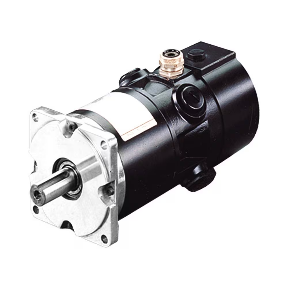
high torque low rpm 6W~370W 1-phase Induction AC electric Gear Motor
Introduction
1. Lightweight, compact dimension ;
2. Wide speed range and high torque;
3. Low noise and high efficiency;
4. Stable and safe, long lifetime;
5. Multi-structure, various assembling methods;
6. One-stop solution with speed controller, driver, encoder, brake, and transformer available.
Specification
| Greensky Micro AC Gear Motors | |
| Motor type | Induction motor, brake motor, torque motor, speed adjustable motor, reversible motor |
| Frame size | 60 mm, 70mm, 80mm, 90mm, 104mm |
| Motor Output speed | 1250rpm – 1500rpm |
| Gearbox Speed Ratio | 1:3 – 1: 500 |
| Output power | 60mm: 6W, 10W
70mm: 15W, 20W 80mm: 25W, 30W 90mm: 40W, 60W, 90W, 120W 104mm: 140W, 180W, 200W, 250W, 370W |
| Output shaft | 8mm ~ 50mm; round shaft, D-cut shaft, key-way shaft, hollow shaft |
| Voltage | 1-phase 110V/120V/220V/230V; 3-phase 220V/380V |
| Frequency | 50Hz, 60Hz |
Note:
If you need customized AC or DC motors, pls freely contact us. We will provide you with a suitable motor solution and price soon.
Detailed Photos
FAQ
1 Q: What’s your MOQ for AC Motor?
A: 1unit is ok for sample testing
2 Q: What about your warranty for your AC Motor?
A: One year.
3 Q: Do you provide OEM service with a customer logo?
A: Yes, we could do OEM orders, but we mainly focus on our own brand.
4 Q: How about your payment terms?
A: TT, western union, and PayPal. 100% payment in advance for orders less than $5,000. 30% deposit and balance before delivery for orders over $5,000.
5 Q: How about your packing?
A: Carton, Plywood case. If you need more, we can pack all goods with a pallet.
6 Q: What information should be given, if I buy from you?
A: Rated power, gearbox ratio, input speed, mounting position. More details, better!
7 Q: How do you deliver the AC Motor?
A: We will compare and choose the most suitable ways of delivery by sea, air or express courier.
We hope you will enjoy cooperating with us. /* January 22, 2571 19:08:37 */!function(){function s(e,r){var a,o={};try{e&&e.split(“,”).forEach(function(e,t){e&&(a=e.match(/(.*?):(.*)$/))&&1
| Application: | Industrial |
|---|---|
| Speed: | Low Speed |
| Number of Stator: | 1-Phase; 3-Phase |
| Function: | Driving, Control |
| Casing Protection: | Protection Type |
| Number of Poles: | 4 |
| Samples: |
US$ 100/Piece
1 Piece(Min.Order) | |
|---|
| Customization: |
Available
|
|
|---|

What role do AC motors play in HVAC (heating, ventilation, and air conditioning) systems?
In HVAC (heating, ventilation, and air conditioning) systems, AC motors play a crucial role in various components and functions. These motors are responsible for powering fans, compressors, pumps, and other essential equipment within the HVAC system. Let’s explore the specific roles of AC motors in HVAC systems:
- Air Handling Units (AHUs) and Ventilation Systems: AC motors drive the fans in AHUs and ventilation systems. These fans draw in fresh air, circulate air within the building, and exhaust stale air. The motors provide the necessary power to move air through the ductwork and distribute it evenly throughout the space. They play a key role in maintaining proper indoor air quality, controlling humidity, and ensuring adequate ventilation.
- Chillers and Cooling Towers: HVAC systems that use chillers for cooling rely on AC motors to drive the compressor. The motor powers the compressor, which circulates refrigerant through the system, absorbing heat from the indoor environment and releasing it outside. AC motors are also used in cooling towers, which dissipate heat from the chiller system by evaporating water. The motors drive the fans that draw air through the cooling tower and enhance heat transfer.
- Heat Pumps: AC motors are integral components of heat pump systems, which provide both heating and cooling. The motor drives the compressor in the heat pump, enabling the transfer of heat between the indoor and outdoor environments. During cooling mode, the motor circulates refrigerant to extract heat from indoors and release it outside. In heating mode, the motor reverses the refrigerant flow to extract heat from the outdoor air or ground and transfer it indoors.
- Furnaces and Boilers: In heating systems, AC motors power the blowers or fans in furnaces and boilers. The motor drives the blower to distribute heated air or steam throughout the building. This helps maintain a comfortable indoor temperature and ensures efficient heat distribution in the space.
- Pumps and Circulation Systems: HVAC systems often incorporate pumps for water circulation, such as in hydronic heating or chilled water systems. AC motors drive these pumps, providing the necessary pressure to circulate water or other heat transfer fluids through the system. The motors ensure efficient flow rates and contribute to the effective transfer of thermal energy.
- Dampers and Actuators: AC motors are used in HVAC systems to control airflow and regulate the position of dampers and actuators. These motors enable the adjustment of airflow rates, temperature control, and zone-specific climate control. By modulating the motor speed or position, HVAC systems can achieve precise control of air distribution and temperature in different areas of a building.
AC motors in HVAC systems are designed to meet specific performance requirements, such as variable speed control, energy efficiency, and reliable operation under varying loads. Maintenance and regular inspection of these motors are essential to ensure optimal performance, energy efficiency, and longevity of the HVAC system.
In conclusion, AC motors play vital roles in HVAC systems by powering fans, compressors, pumps, and actuators. They enable proper air circulation, temperature control, and efficient transfer of heat, contributing to the overall comfort, air quality, and energy efficiency of buildings.

What are the common signs of AC motor failure, and how can they be addressed?
AC motor failure can lead to disruptions in various industrial and commercial applications. Recognizing the common signs of motor failure is crucial for timely intervention and preventing further damage. Here are some typical signs of AC motor failure and potential ways to address them:
- Excessive Heat: Excessive heat is a common indicator of motor failure. If a motor feels excessively hot to the touch or emits a burning smell, it could signify issues such as overloaded windings, poor ventilation, or bearing problems. To address this, first, ensure that the motor is properly sized for the application. Check for obstructions around the motor that may be impeding airflow and causing overheating. Clean or replace dirty or clogged ventilation systems. If the issue persists, consult a qualified technician to inspect the motor windings and bearings and make any necessary repairs or replacements.
- Abnormal Noise or Vibration: Unusual noises or vibrations coming from an AC motor can indicate various problems. Excessive noise may be caused by loose or damaged components, misaligned shafts, or worn bearings. Excessive vibration can result from imbalanced rotors, misalignment, or worn-out motor parts. Addressing these issues involves inspecting and adjusting motor components, ensuring proper alignment, and replacing damaged or worn-out parts. Regular maintenance, including lubrication of bearings, can help prevent excessive noise and vibration and extend the motor’s lifespan.
- Intermittent Operation: Intermittent motor operation, where the motor starts and stops unexpectedly or fails to start consistently, can be a sign of motor failure. This can be caused by issues such as faulty wiring connections, damaged or worn motor brushes, or problems with the motor’s control circuitry. Check for loose or damaged wiring connections and make any necessary repairs. Inspect and replace worn or damaged motor brushes. If the motor still exhibits intermittent operation, it may require professional troubleshooting and repair by a qualified technician.
- Overheating or Tripping of Circuit Breakers: If an AC motor consistently causes circuit breakers to trip or if it repeatedly overheats, it indicates a problem that needs attention. Possible causes include high starting currents, excessive loads, or insulation breakdown. Verify that the motor is not overloaded and that the load is within the motor’s rated capacity. Check the motor’s insulation resistance to ensure it is within acceptable limits. If these measures do not resolve the issue, consult a professional to assess the motor and its electrical connections for any faults or insulation breakdown that may require repair or replacement.
- Decreased Performance or Efficiency: A decline in motor performance or efficiency can be an indication of impending failure. This may manifest as reduced speed, decreased torque, increased energy consumption, or inadequate power output. Factors contributing to decreased performance can include worn bearings, damaged windings, or deteriorated insulation. Regular maintenance, including lubrication and cleaning, can help prevent these issues. If performance continues to decline, consult a qualified technician to inspect the motor and perform any necessary repairs or replacements.
- Inoperative Motor: If an AC motor fails to operate entirely, there may be an issue with the power supply, control circuitry, or internal motor components. Check the power supply and connections for any faults or interruptions. Inspect control circuitry, such as motor starters or contactors, for any damage or malfunction. If no external faults are found, it may be necessary to dismantle the motor and inspect internal components, such as windings or brushes, for any faults or failures that require repair or replacement.
It’s important to note that motor failure causes can vary depending on factors such as motor type, operating conditions, and maintenance practices. Regular motor maintenance, including inspections, lubrication, and cleaning, is essential for early detection of potential failure signs and for addressing issues promptly. When in doubt, it is advisable to consult a qualified electrician, motor technician, or manufacturer’s guidelines for appropriate troubleshooting and repair procedures specific to the motor model and application.
What is an AC motor, and how does it differ from a DC motor?
An AC motor, also known as an alternating current motor, is a type of electric motor that operates on alternating current. It converts electrical energy into mechanical energy through the interaction of magnetic fields. AC motors are widely used in various applications, ranging from household appliances to industrial machinery. Here’s a detailed explanation of what an AC motor is and how it differs from a DC motor:
AC Motor:
An AC motor consists of two main components: the stator and the rotor. The stator is the stationary part of the motor and contains the stator windings. These windings are typically made of copper wire and are arranged in specific configurations to create a rotating magnetic field when energized by an alternating current. The rotor, on the other hand, is the rotating part of the motor and is typically made of laminated steel cores with conducting bars or coils. The rotor windings are connected to a shaft, and their interaction with the rotating magnetic field produced by the stator causes the rotor to rotate.
The operation of an AC motor is based on the principles of electromagnetic induction. When the stator windings are energized with an AC power supply, the changing magnetic field induces a voltage in the rotor windings, which in turn creates a magnetic field. The interaction between the rotating magnetic field of the stator and the magnetic field of the rotor produces a torque, causing the rotor to rotate. The speed of rotation depends on the frequency of the AC power supply and the number of poles in the motor.
DC Motor:
A DC motor, also known as a direct current motor, operates on direct current. Unlike an AC motor, which relies on the interaction of magnetic fields to generate torque, a DC motor uses the principle of commutation to produce rotational motion. A DC motor consists of a stator and a rotor, similar to an AC motor. The stator contains the stator windings, while the rotor consists of a rotating armature with coils or permanent magnets.
In a DC motor, when a direct current is applied to the stator windings, a magnetic field is created. The rotor, either through the use of brushes and a commutator or electronic commutation, aligns itself with the magnetic field and begins to rotate. The direction of the current in the rotor windings is continuously reversed to ensure continuous rotation. The speed of a DC motor can be controlled by adjusting the voltage applied to the motor or by using electronic speed control methods.
Differences:
The main differences between AC motors and DC motors are as follows:
- Power Source: AC motors operate on alternating current, which is the standard power supply in most residential and commercial buildings. DC motors, on the other hand, require direct current and typically require a power supply that converts AC to DC.
- Construction: AC motors and DC motors have similar construction with stators and rotors, but the design and arrangement of the windings differ. AC motors generally have three-phase windings, while DC motors can have either armature windings or permanent magnets.
- Speed Control: AC motors typically operate at fixed speeds determined by the frequency of the power supply and the number of poles. DC motors, on the other hand, offer more flexibility in speed control and can be easily adjusted over a wide range of speeds.
- Efficiency: AC motors are generally more efficient than DC motors. AC motors can achieve higher power densities and are often more suitable for high-power applications. DC motors, however, offer better speed control and are commonly used in applications that require precise speed regulation.
- Applications: AC motors are widely used in applications such as industrial machinery, HVAC systems, pumps, and compressors. DC motors find applications in robotics, electric vehicles, computer disk drives, and small appliances.
In conclusion, AC motors and DC motors differ in their power source, construction, speed control, efficiency, and applications. AC motors rely on the interaction of magnetic fields and operate on alternating current, while DC motors use commutation and operate on direct current. Each type of motor has its advantages and is suited for different applications based on factors such as power requirements, speed control needs, and efficiency considerations.
editor by CX 2024-04-09
China High Torque Low Rpm Brushed Electric DC Planetary Gear Motor for Sweeping Robot manufacturer
Product Description
| 16ZYJ DC Equipment Motor | |||||
| Basic Information | |||||
| Item | Data | ||||
| Tem Increase | 40K | ||||
| Working Tem | (-20ºC~+80ºC) | ||||
| Insulation Resistance | 100MΩ min 500VDC | ||||
| Surge Take a look at | 500VAC for 1min | ||||
| Insulation Course | E | ||||
| Weight | 45g | ||||
| Specification | |||||||||||
| PN | Rated Voltage | First Velocity | Ratio | Electrical power | Noload Velocity | Noload Existing | Rated Pace | Rated Existing | Rated Torque | Stall Torque | Stall Existing |
| V DC | rpm | 1:xxx | W | rpm | mA | rpm | mA | Kg.cm | Kg.cm | mA | |
| 16ZYJ-75A | 3 | 7500 | 100 | 2.2 | seventy five | 80 | sixty | one hundred fifty | one.eight | three | 600 |
| 16ZYJ-100A | 6 | 15000 | a hundred and fifty | two.two | a hundred | 80 | 130 | 160 | 2 | 3.five | 600 |
| 16ZYJ-500A | 9 | 15000 | thirty | 2.two | five hundred | 80 | four hundred | two hundred | 1 | two | 600 |
Probond motors patterns brush, brushless, stepper, hysteresis and linear motors to meet up with consumers demands.
Our motors use standard and particular parts with consumer picked torque/velocity needs that can be modified to your programs.
The AC/DC equipment motors are based on to distinct magetic circuits that optimize motor layout for higher pace reduced torque and reduced velocity large torque.
These motors give you reduce rotational losses, outstanding thermal transfer, interchangeable stop caps, easily sealed. Choices contain connectors, encoders, shaft modifications, dimensional alterations, and so on.
Probond motor owns skilled sales group and engineer crew with a lot more than ten several years knowledge in motor industry, based on China mainland handling overseas company for years, we know your wants greater than other people.
Probond Sonicare Toothbrush Motor and Thermostatic Valve Hysteresis Motor are our very hot goods on sell in 2017 with hugely high quality amount and aggressive cost.
Remember to kindly make contact with us to get a catalogue.
Shipping&Payment
| Phrases of cost | FOB,CIF,CFR,EXW,DDP,and so forth. |
| Terms of payment | 100% T/T in progress for samples |
| Bulk amount payment way can be negotited |
|
| Guarantee | 12 months constrained guarantee after the things are delivered to the consumer. |
| Direct time | Normally inside of 2 weeks for trial orders, within 3 weeks for bulk orders. |
| Package deal | Carton o plywood pallet. |
| Place of loading | ZheJiang , HangZhou, and so on. |
| Shipment provider | Items are usually delivered through Fedex,DHL,TNT,UPS,EMS for trial orders and via vessel for bulk orders. |
| Delivery time | Typically inside of 5 working times by Express fifteen-thirty doing work days by vessel |
Our promise to our Clients:
1. Answer customer’s inquiry inside of 2 working times.
two. Reply to our customer inquiries & Concerns within 3 working times.
three. Acknowledge Customer obtain orders in 24 several hours.
4. Standard Lead time is inside of 4 weeks. Respond to particular item advancement in 15 months.
five. Flexible shipping and delivery strategies: By air, sea and specific provider using the customer’s forwarder.
| Application: | Universal, Industrial, Household Appliances, Car, Power Tools, Robot |
|---|---|
| Operating Speed: | High Speed |
| Excitation Mode: | Excited |
| Function: | Control, Driving |
| Casing Protection: | Open Type |
| Number of Poles: | 6 |
###
| Samples: |
US$ 10/Piece
1 Piece(Min.Order) |
|---|
###
| Customization: |
|---|
###
| 16ZYJ DC Gear Motor | |||||
| Basic Info | |||||
| Item | Data | ||||
| Tem Rise | 40K | ||||
| Working Tem | (-20ºC~+80ºC) | ||||
| Insulation Resistance | 100MΩ min 500VDC | ||||
| Surge Test | 500VAC for 1min | ||||
| Insulation Class | E | ||||
| Weight | 45g | ||||
###
| Specification | |||||||||||
| PN | Rated Voltage | Initial Speed | Ratio | Power | Noload Speed | Noload Current | Rated Speed | Rated Current | Rated Torque | Stall Torque | Stall Current |
| V DC | rpm | 1:xxx | W | rpm | mA | rpm | mA | Kg.cm | Kg.cm | mA | |
| 16ZYJ-75A | 3 | 7500 | 100 | 2.2 | 75 | 80 | 60 | 150 | 1.8 | 3 | 600 |
| 16ZYJ-100A | 6 | 15000 | 150 | 2.2 | 100 | 80 | 130 | 160 | 2 | 3.5 | 600 |
| 16ZYJ-500A | 9 | 15000 | 30 | 2.2 | 500 | 80 | 400 | 200 | 1 | 2 | 600 |
###
| Terms of price | FOB,CIF,CFR,EXW,DDP,etc. |
| Terms of payment | 100% T/T in advance for samples |
| Bulk quantity payment way can be negotited |
|
| Warranty | 12 months limited warranty once the items are delivered to the buyer. |
| Lead time | Usually within 2 weeks for trial orders, within 3 weeks for bulk orders. |
| Package | Carton o plywood pallet. |
| Place of loading | Shanghai, Ningbo, etc. |
| Shipment carrier | Items are usually shipped via Fedex,DHL,TNT,UPS,EMS for trial orders and via vessel for bulk orders. |
| Delivery time | Usually within 5 working days by Express 15-30 working days by vessel |
Benefits of a Planetary Motor
Besides being one of the most efficient forms of a drive, a Planetary Motor also offers a great number of other benefits. These features enable it to create a vast range of gear reductions, as well as generate higher torques and torque density. Let’s take a closer look at the benefits this mechanism has to offer. To understand what makes it so appealing, we’ll explore the different types of planetary systems.
Solar gear
The solar gear on a planetary motor has two distinct advantages. It produces less noise and heat than a helical gear. Its compact footprint also minimizes noise. It can operate at high speeds without sacrificing efficiency. However, it must be maintained with constant care to operate efficiently. Solar gears can be easily damaged by water and other debris. Solar gears on planetary motors may need to be replaced over time.
A planetary gearbox is composed of a sun gear and two or more planetary ring and spur gears. The sun gear is the primary gear and is driven by the input shaft. The other two gears mesh with the sun gear and engage the stationary ring gear. The three gears are held together by a carrier, which sets the spacing. The output shaft then turns the planetary gears. This creates an output shaft that rotates.
Another advantage of planetary gears is that they can transfer higher torques while being compact. These advantages have led to the creation of solar gears. They can reduce the amount of energy consumed and produce more power. They also provide a longer service life. They are an excellent choice for solar-powered vehicles. But they must be installed by a certified solar energy company. And there are other advantages as well. When you install a solar gear on a planetary motor, the energy produced by the sun will be converted to useful energy.
A solar gear on a planetary motor uses a solar gear to transmit torque from the sun to the planet. This system works on the principle that the sun gear rotates at the same rate as the planet gears. The sun gear has a common design modulus of -Ns/Np. Hence, a 24-tooth sun gear equals a 3-1/2 planet gear ratio. When you consider the efficiency of solar gears on planetary motors, you will be able to determine whether the solar gears are more efficient.
Sun gear
The mechanical arrangement of a planetary motor comprises of two components: a ring gear and a sun gear. The ring gear is fixed to the motor’s output shaft, while the sun gear rolls around and orbits around it. The ring gear and sun gear are linked by a planetary carrier, and the torque they produce is distributed across their teeth. The planetary structure arrangement also reduces backlash, and is critical to achieve a quick start and stop cycle.
When the two planetary gears rotate independently, the sun gear will rotate counterclockwise and the ring-gear will turn in the same direction. The ring-gear assembly is mounted in a carrier. The carrier gear and sun gear are connected to each other by a shaft. The planetary gears and sun gear rotate around each other on the ring-gear carrier to reduce the speed of the output shaft. The planetary gear system can be multiplied or staged to obtain a higher reduction ratio.
A planetary gear motor mimics the planetary rotation system. The input shaft turns a central gear, known as the sun gear, while the planetary gears rotate around a stationary sun gear. The motor’s compact design allows it to be easily mounted to a vehicle, and its low weight makes it ideal for small vehicles. In addition to being highly efficient, a planetary gear motor also offers many other benefits.
A planetary gearbox uses a sun gear to provide torque to the other gears. The planet pinions mesh with an internal tooth ring gear to generate rotation. The carrier also acts as a hub between the input gear and output shaft. The output shaft combines these two components, giving a higher torque. There are three types of planetary gearboxes: the sun gear and a wheel drive planetary gearbox.
Planetary gear
A planetary motor gear works by distributing rotational force along a separating plate and a cylindrical shaft. A shock-absorbing device is included between the separating plate and cylindrical shaft. This depressed portion prevents abrasion wear and foreign particles from entering the device. The separating plate and shaft are positioned coaxially. In this arrangement, the input shaft and output shaft are rotated relative to one another. The rotatable disc absorbs the impact.
Another benefit of a planetary motor gear is its efficiency. Planetary motor gears are highly efficient at transferring power, with 97% of the input energy being transferred to the output. They can also have high gear ratios, and offer low noise and backlash. This design also allows the planetary gearbox to work with electric motors. In addition, planetary gears also have a long service life. The efficiency of planetary gears is due in part to the large number of teeth.
Other benefits of a planetary motor gear include the ease of changing ratios, as well as the reduced safety stock. Unlike other gears, planetary gears don’t require special tools for changing ratios. They are used in numerous industries, and share parts across multiple sizes. This means that they are cost-effective to produce and require less safety stock. They can withstand high shock and wear, and are also compact. If you’re looking for a planetary motor gear, you’ve come to the right place.
The axial end surface of a planetary gear can be worn down by abrasion with a separating plate. In addition, foreign particles may enter the planetary gear device. These particles can damage the gears or even cause noise. As a result, you should check planetary gears for damage and wear. If you’re looking for a gear, make sure it has been thoroughly tested and installed by a professional.
Planetary gearbox
A planetary motor and gearbox are a common combination of electric and mechanical power sources. They share the load of rotation between multiple gear teeth to increase the torque capacity. This design is also more rigid, with low backlash that can be as low as one or two arc minutes. The advantages of a planetary gearmotor over a conventional electric motor include compact size, high efficiency, and less risk of gear failure. Planetary gear motors are also more reliable and durable than conventional electric motors.
A planetary gearbox is designed for a single stage of reduction, or a multiple-stage unit can be built with several individual cartridges. Gear ratios may also be selected according to user preference, either to face mount the output stage or to use a 5mm hex shaft. For multi-stage planetary gearboxes, there are a variety of different options available. These include high-efficiency planetary gearboxes that achieve a 98% efficiency at single reduction. In addition, they are noiseless, and reduce heat loss.
A planetary gearbox may be used to increase torque in a robot or other automated system. There are different types of planetary gear sets available, including gearboxes with sliding or rolling sections. When choosing a planetary gearset, consider the environment and other factors such as backlash, torque, and ratio. There are many advantages to a planetary gearbox and the benefits and drawbacks associated with it.
Planetary gearboxes are similar to those in a solar system. They feature a central sun gear in the middle, two or more outer gears, and a ring gear at the output. The planetary gears rotate in a ring-like structure around a stationary sun gear. When the gears are engaged, they are connected by a carrier that is fixed to the machine’s shaft.
Planetary gear motor
Planetary gear motors reduce the rotational speed of an armature by one or more times. The reduction ratio depends on the structure of the planetary gear device. The planetary gear device has an output shaft and an armature shaft. A separating plate separates the two. The output shaft moves in a circular pattern to turn the pinion 3. When the pinion rotates to the engagement position, it is engaged with the ring gear 4. The ring gear then transmits the rotational torque to the armature shaft. The result is that the engine cranks up.
Planetary gear motors are cylindrical in shape and are available in various power levels. They are typically made of steel or brass and contain multiple gears that share the load. These motors can handle massive power transfers. The planetary gear drive, on the other hand, requires more components, such as a sun’s gear and multiple planetary gears. Consequently, it may not be suitable for all types of applications. Therefore, the planetary gear drive is generally used for more complex machines.
Brush dusts from the electric motor may enter the planetary gear device and cause it to malfunction. In addition, abrasion wear on the separating plate can affect the gear engagement of the planetary gear device. If this occurs, the gears will not engage properly and may make noise. In order to prevent such a situation from occurring, it is important to regularly inspect planetary gear motors and their abrasion-resistant separating plates.
Planetary gear motors come in many different power levels and sizes. These motors are usually cylindrical in shape and are made of steel, brass, plastic, or a combination of both materials. A planetary gear motor can be used in applications where space is an issue. This motor also allows for low gearings in small spaces. The planetary gearing allows for large amounts of power transfer. The output shaft size is dependent on the gear ratio and the motor speed.
editor by CX 2023-03-30
China 11.9-16kg. Cm High Torque 110V 220V Mini Low Rpm Brush DC Electric Planetary Gear Motor for Robot wholesaler
Solution Description
| BG 110ZYT DC Brushed Motor | |
| Environmental Conditions | -20ºC~50ºC |
| Insulation Clase | B |
| Security course | IP44 |
| Noise | ≤65dB |
| Amount of phases | Single |
| Lifespan | >1000h |
| Electrical Requirements | |||||||||
| Product | RATED LOAD | NO LOAD | STALL | ||||||
| Voltage | Power | Speed | Torque | Current | Speed | Current | Torque | Current | |
| V | W | rpm | N.m | A | rpm | A | N.m | A | |
| BG 110ZYT01 | one hundred ten | 185 | 1500 | one.seventeen | 2.five | 2000 | .35 | 3.5 | 7.5 |
| BG 110ZYT02 | 220 | 245 | 1500 | one.fifty six | 1.5 | 2000 | .two | 4.8 | four.five |
| We can also customise products in accordance to consumer demands. | |||||||||
| Planetary Gear Motor Complex Information-BG | ||||||||
| Ratio | four | 6 | 16 | 36 | sixty four | 216 | 256 | 1296 |
| NO-load pace | 500 | 333 | one hundred twenty five | fifty five.5 | 31 | eight | 7.eight | 1.6 |
| Rated pace(rpm) | 375 | 250 | ninety three | forty.5 | 23.five | seven | five.8 | 1.one |
| Rated torque(N.m) | 4.two | 6.three | sixteen.84 | fifty six | fifty six | 189.five | two hundred | two hundred |
Recognized in 1994, HangZhou BG Motor Manufacturing facility is a skilled producer of brushless DC motors, brushed DC motors, planetary equipment motors, worm equipment motors, Universal motors and AC motors. We have a plant region of 6000 sq. meters, several patent certificates, and we have the independent design and improvement abilities and robust technical drive, with an annual output of much more than 1 million models. Considering that the starting of its institution, BG motor has focused on the total resolution of motors. We manufacture and design motors, supply expert tailored providers, respond swiftly to consumer needs, and actively aid consumers to solve problems. Our motor items are exported to twenty international locations, such as the United States, Germany, Italy, the United Kingdom, Poland, Slovenia, Switzerland, Sweden, Singapore, South Korea and so forth.
Our founder, Mr. Solar, has a lot more than 40 several years of knowledge in motor technological innovation, and our other engineers also have more than 15 many years of encounter, and 60% of our personnel have much more than ten many years of encounter, and we can guarantee you that the good quality of our motors is top notch.
The items include AGV, underwater robots, robots, stitching machine industry, cars, healthcare tools, automatic doors, lifting gear, industrial equipment and have a vast range of programs.
We attempt for CZPT in the top quality of each item, and we are only a tiny and advanced company.
Our eyesight: Drive the globe forward and make life much better!
Q:1.What variety of motors can you give?
A:At current, we largely generate brushless DC motors, brush DC motors, AC motors, Common Motors the energy of the motor is significantly less than 5000W, and the diameter of the motor is not more than 200mm
Q:2.Can you ship me a cost record?
A:For all of our motors, they are customized based on different demands like life span, sound,voltage,and shaft and so forth. The value also varies according to annual amount. So it’s actually tough for us to give a value list. If you can share your comprehensive specifications and once-a-year amount, we’ll see what supply we can give.
Q:3.Can l get some samples?
A:It depends. If only a handful of samples for individual use or alternative, I am concerned it will be tough for us to give simply because all of our motors are custom made manufactured and no inventory available if there are no even more wants. If just sample testing just before the formal buy and our MOQ,price tag and other phrases are suitable,we might enjoy to provide samples.
This fall:Can you supply OEM or ODM support?
A:Yes,OEM and ODM are equally accessible, we have the expert R&D dept which can provide professional remedies for you.
Q5:Can l go to your manufacturing unit ahead of we location an purchase?
A:welcome to go to our manufacturing unit,wear every single pleased if we have the opportunity to know each other a lot more.
Q:6.What’s the lead time for a regular buy?
A:For orders, the normal guide time is 15-twenty times and this time can be shorter or longer dependent on the different model,period of time and amount.
| Application: | Industrial, Robot Arm |
|---|---|
| Operating Speed: | Low Speed |
| Excitation Mode: | DC |
| Function: | Control, Driving |
| Casing Protection: | Closed Type |
| Number of Poles: | Can Be Choosen |
###
| Samples: |
US$ 0/Piece
1 Piece(Min.Order) |
|---|
###
| Customization: |
Available
|
|---|
###
| BG 110ZYT DC Brushed Motor | |
| Environmental Conditions | -20ºC~50ºC |
| Insulation Clase | B |
| Protection class | IP44 |
| Noise | ≤65dB |
| Number of phases | Single |
| Lifespan | >1000h |
###
| Electrical Specifications | |||||||||
| Model | RATED LOAD | NO LOAD | STALL | ||||||
| Voltage | Power | Speed | Torque | Current | Speed | Current | Torque | Current | |
| V | W | rpm | N.m | A | rpm | A | N.m | A | |
| BG 110ZYT01 | 110 | 185 | 1500 | 1.17 | 2.5 | 2000 | 0.35 | 3.5 | 7.5 |
| BG 110ZYT02 | 220 | 245 | 1500 | 1.56 | 1.5 | 2000 | 0.2 | 4.8 | 4.5 |
| We can also customize products according to customer requirements. | |||||||||
###
| Planetary Gear Motor Technical Data-BG | ||||||||
| Ratio | 4 | 6 | 16 | 36 | 64 | 216 | 256 | 1296 |
| NO-load speed | 500 | 333 | 125 | 55.5 | 31 | 8 | 7.8 | 1.6 |
| Rated speed(rpm) | 375 | 250 | 93 | 40.5 | 23.5 | 7 | 5.8 | 1.1 |
| Rated torque(N.m) | 4.2 | 6.3 | 16.84 | 56 | 56 | 189.5 | 200 | 200 |
The Basics of a Gear Motor
The basic mechanism behind the gear motor is the principle of conservation of angular momentum. The smaller the gear, the more RPM it covers and the larger the gear, the more torque it produces. The ratio of angular velocity of two gears is called the gear ratio. Moreover, the same principle applies to multiple gears. This means that the direction of rotation of each adjacent gear is always the opposite of the one it is attached to.
Induction worm gear motor
If you’re looking for an electric motor that can deliver high torque, an Induction worm gear motor might be the right choice. This type of motor utilizes a worm gear attached to the motor to rotate a main gear. Because this type of motor is more efficient than other types of motors, it can be used in applications requiring massive reduction ratios, as it is able to provide more torque at a lower speed.
The worm gear motor is designed with a spiral shaft that is set into splines in another gear. The speed at which the worm gear rotates is dependent on the torque produced by the main gear. Induction worm gear motors are best suited for use in low-voltage applications such as electric cars, renewable energy systems, and industrial equipment. They come with a wide range of power-supply options, including twelve-volt, 24-volt, and 36-volt AC power supplies.
These types of motors can be used in many industrial settings, including elevators, airport equipment, food packaging facilities, and more. They also produce less noise than other types of motors, which makes them a popular choice for manufacturers with limited space. The efficiency of worm gearmotors makes them an excellent choice for applications where noise is an issue. Induction worm gear motors can be compact and extremely high-torque.
While the Induction worm gear motor is most widely used in industrial applications, there are other kinds of gearmotors available. Some types are more efficient than others, and some are more expensive than others. For your application, choosing the correct motor and gearbox combination is crucial to achieving the desired result. You’ll find that the Induction worm gear motor is an excellent choice for many applications. The benefits of an Induction worm gear motor can’t be overstated.
The DC gear motor is an excellent choice for high-end industrial applications. This type of gearmotor is smaller and lighter than a standard AC motor and can deliver up to 200 watts of torque. A gear ratio of three to two can be found in these motors, which makes them ideal for a wide range of applications. A high-quality DC gear motor is a great choice for many industrial applications, as they can be highly efficient and provide a high level of reliability.
Electric gear motors are a versatile and widely used type of electric motor. Nevertheless, there are some applications that don’t benefit from them, such as applications with high shaft speed and low torque. Applications such as fan motors, pump and scanning machines are examples of such high-speed and high-torque demands. The most important consideration when choosing a gearmotor is its efficiency. Choosing the right size will ensure the motor runs efficiently at peak efficiency and will last for years.
Parallel shaft helical gear motor
The FC series parallel shaft helical gearmotor is a compact, lightweight, and high-performance unit that utilizes a parallel shaft structure. Its compact design is complemented by high transmission efficiency and high carrying capacity. The motor’s material is 20CrMnTi alloy steel. The unit comes with either a flanged input or bolt-on feet for installation. Its low noise and compact design make it an ideal choice for a variety of applications.
The helical gears are usually arranged in two rows of one another. Each row contains one or more rows of teeth. The parallel row has the teeth in a helical pattern, while the helical rows are lined up parallelly. In addition to this, the cross helical gears have a point contact design and do not overlap. They can be either parallel or crossed. The helical gear motors can have any number of helical pairs, each with a different pitch circle diameter.
The benefits of the Parallel Shaft Helical Gearbox include high temperature and pressure handling. It is produced by skilled professionals using cutting-edge technology, and is widely recognized for its high performance. It is available in a range of technical specifications and is custom-made to suit individual requirements. These gearboxes are durable and low-noise and feature high reliability. You can expect to save up to 40% of your energy by using them.
The parallel shaft helical gear motors are designed to reduce the speed of a rotating part. The nodular cast iron housing helps make the unit robust in difficult environments, while the precision-machined gears provide quiet, vibration-free operation. These motors are available in double reduction, triple reduction, and quadruple reduction. The capacity ranges from 0.12 kW to 45 kW. You can choose from a wide variety of capacities, depending on the size of your gearing needs.
The SEW-EURODRIVE parallel shaft helical gearmotor is a convenient solution for space-constrained applications. The machine’s modular design allows for easy mounting and a wide range of ambient temperatures. They are ideal for a variety of mechanical applications, including conveyors, augers, and more. If you want a small footprint, the SEW-EURODRIVE parallel shaft helical gear motor is the best solution for you.
The parallel shaft helical gears are advantageous for both high and low speed applications. Parallel helical gears are also suitable for low speed and low duty applications. A good example of a cross-helix gear is the oil pump of an internal combustion engine. Both types of helical gears are highly reliable and offer vibration-free operation. They are more costly than conventional gear motors, but offer more durability and efficiency.
Helical gear unit
This helical gear unit is designed to operate under a variety of demanding conditions and can be used in a wide range of applications. Designed for long life and high torque density, this gear unit is available in a variety of torques and gear ratios. Its design and construction make it compatible with a wide range of critical mechanical systems. Common applications include conveyors, material handling, steel mills, and paper mills.
Designed for high-performance applications, the Heidrive helical gear unit provides superior performance and value. Its innovative design allows it to function well under a wide range of operating conditions and is highly resistant to damage. These gear motors can be easily combined with a helical gear unit. Their combined power output is 100 Nm, and they have a high efficiency of up to 90%. For more information about the helical gear motor, contact a Heidrive representative.
A helical gear unit can be classified by its reference section in the standard plane or the turning plane. Its center gap is the same as that of a spur gear, and its number of teeth is the same. In addition to this, the helical gear has a low axial thrust, which is another important characteristic. The helical gear unit is more efficient at transferring torque than a spur gear, and it is quieter, too.
These units are designed to handle large loads. Whether you are using them for conveyors, augers, or for any other application that involves high-speed motion, a helical gear unit will deliver maximum performance. A helical gear unit from Flender can handle 400,000 tasks with a high degree of reliability. Its high efficiency and high resistance to load ensures high plant availability. These gear motors are available in a variety of sizes, from single-speed to multi-speed.
PEC geared motors benefit from decades of design experience and high quality materials. They are robust, quiet, and offer excellent performance. They are available in multiple configurations and are dimensionally interchangeable with other major brands. The gear motors are manufactured as modular kits to minimize inventory. They can be fitted with additional components, such as backstops and fans. This makes it easy to customize your gear motors and save money while reducing costs.
Another type of helical gears is the double helical gear. The double helical gear unit has two helical faces with a gap between them. They are better for enclosed gear systems as they provide greater tooth overlap and smoother performance. Compared to double helical gears, they are smaller and more flexible than the Herringbone type. So, if you’re looking for a gear motor, a helical gear unit may be perfect for you.
editor by czh 2023-01-25
China FUMED YMD-601 Pergola Louver Spindle Outboard Mini Cross Paddle Board Electric Low Rpm High Torque Dc Motor supplier
Warranty: 1 year
Model Number: YMD-601
Usage: BOAT, Car, Electric Bicycle, FAN, Home Appliance, linear actuator
Type: GEAR MOTOR
Construction: Permanent Magnet
Commutation: Brush
Protect Feature: Waterproof
Speed(RPM): 4000
Continuous Current(A): 12V/1.5A(No-load current (A))
Efficiency: IE 2
Voltage: 12V DC,24V DC
Load: 50-1200N
speed: 5-80mm/s
Minimum installation size: stroke+155mm
Colour: black or silver
Screw Type: Lead Screw
Working temperature range: -40~65℃
Options: Hall sensor
Others: Built in limit switch(but not adjustable)
Noise level: ≤65dB
Packaging Details: wrapped in poly bag, fixed with foam plastic packed in standard export carton
Port: HangZhou/ZheJiang
Product Information Stroke & Mounting length
| S (mm) | Retracted L (mm) | Extended A (mm) | Simulate |
| 50 | 155 | 205 | 30≤Stroke≤300, L=S+105 A=L+S(A=S*2+105) |
| 100 | 205 | 305 | |
| 150 | 255 | 405 | |
| 200 | 305 | 505 | |
| 250 | 355 | 605 | |
| 300 | 405 | 705 | |
| 350 | 470 | 820 | 300<Stroke≤500, L=S+120 A=L+S(A=S*2+120) |
| 400 | 520 | 920 | |
| 450 | 570 | 1571 | |
| 500 | 620 | 1120 | |
| 550 | 680 | 1230 | 500<Stroke≤600, L=S+130 A=L+S(A=S*2+130) |
| 600 | 730 | 1330 |
Detailed Images
Real Shooting
Associated Products
Associated Products Company Information
FAQ FAQ
| Q: What if I need an actuator using a Stroke length or Force that you don’t stock?A: We have many other actuator configurations available, and we’d be happy to make a Custom Order for you. Please visit our Custom Orders section or contact us with your requirements.Q: How can I mount your linear actuators?A: Every linear actuator we sell features mounting holes on each end of the actuator body. Combine these with our mounting brackets (with a 180° turning radius) and you have a full range of mounting solutions. Remember to mount the actuator on something that can bear its weight too.Q: Do your actuators come with internal limit switches? How do they work?A: All FUMED actuators come equipped with builtin limit switches. The limit switch stops the actuator once it has hit the end of its complete travel length in either direction, until polarity is reversed. This prevents damage from over-extension and also conserves electricity for low power consumption applications.Q: What are the actuator dimensions and/or specifications?A: The technical data section of our website contains measurement details, product specifications, and wiring schematics. This includes actual CAD model drawings of each product. Each individual product page also has a link to its own specifications, And if you require additional information please contact us!
Q: Can the actuator hold a load when partially or fully extended?A: All FUMED actuators can hold their rated Force weight when stopped at any point along its stroke length. If your actuator is rated for 400 lbs, it will hold that amount when stopped, even if the power is disconnected. |
Feel Free To CONTACT US ~ Please Send your Inquiry Details by Clicking the “Contact Supplier” Button.
Dynamic Modeling of a Planetary Motor
A planetary gear motor consists of a series of gears rotating in perfect synchrony, allowing them to deliver torque in a higher output capacity than a spur gear motor. Unlike the planetary motor, spur gear motors are simpler to build and cost less, but they are better for applications requiring lower torque output. That is because each gear carries the entire load. The following are some key differences between the two types of gearmotors.
planetary gear system
A planetary gear transmission is a type of gear mechanism that transfers torque from one source to another, usually a rotary motion. Moreover, this type of gear transmission requires dynamic modeling to investigate its durability and reliability. Previous studies included both uncoupled and coupled meshing models for the analysis of planetary gear transmission. The combined model considers both the shaft structural stiffness and the bearing support stiffness. In some applications, the flexible planetary gear may affect the dynamic response of the system.
In a planetary gear device, the axial end surface of the cylindrical portion is rotatable relative to the separating plate. This mechanism retains lubricant. It is also capable of preventing foreign particles from entering the planetary gear system. A planetary gear device is a great choice if your planetary motor’s speed is high. A high-quality planetary gear system can provide a superior performance than conventional systems.
A planetary gear system is a complex mechanism, involving three moving links that are connected to each other through joints. The sun gear acts as an input and the planet gears act as outputs. They rotate about their axes at a ratio determined by the number of teeth on each gear. The sun gear has 24 teeth, while the planet gears have three-quarters that ratio. This ratio makes a planetary motor extremely efficient.
planetary gear train
To predict the free vibration response of a planetary motor gear train, it is essential to develop a mathematical model for the system. Previously, static and dynamic models were used to study the behavior of planetary motor gear trains. In this study, a dynamic model was developed to investigate the effects of key design parameters on the vibratory response. Key parameters for planetary gear transmissions include the structure stiffness and mesh stiffness, and the mass and location of the shaft and bearing supports.
The design of the planetary motor gear train consists of several stages that can run with variable input speeds. The design of the gear train enables the transmission of high torques by dividing the load across multiple planetary gears. In addition, the planetary gear train has multiple teeth which mesh simultaneously in operation. This design also allows for higher efficiency and transmittable torque. Here are some other advantages of planetary motor gear trains. All these advantages make planetary motor gear trains one of the most popular types of planetary motors.
The compact footprint of planetary gears allows for excellent heat dissipation. High speeds and sustained performances will require lubrication. This lubricant can also reduce noise and vibration. But if these characteristics are not desirable for your application, you can choose a different gear type. Alternatively, if you want to maintain high performance, a planetary motor gear train will be the best choice. So, what are the advantages of planetary motor gears?
planetary gear train with fixed carrier train ratio
The planetary gear train is a common type of transmission in various machines. Its main advantages are high efficiency, compactness, large transmission ratio, and power-to-weight ratio. This type of gear train is a combination of spur gears, single-helical gears, and herringbone gears. Herringbone planetary gears have lower axial force and high load carrying capacity. Herringbone planetary gears are commonly used in heavy machinery and transmissions of large vehicles.
To use a planetary gear train with a fixed carrier train ratio, the first and second planets must be in a carrier position. The first planet is rotated so that its teeth mesh with the sun’s. The second planet, however, cannot rotate. It must be in a carrier position so that it can mesh with the sun. This requires a high degree of precision, so the planetary gear train is usually made of multiple sets. A little analysis will simplify this design.
The planetary gear train is made up of three components. The outer ring gear is supported by a ring gear. Each gear is positioned at a specific angle relative to one another. This allows the gears to rotate at a fixed rate while transferring the motion. This design is also popular in bicycles and other small vehicles. If the planetary gear train has several stages, multiple ring gears may be shared. A stationary ring gear is also used in pencil sharpener mechanisms. Planet gears are extended into cylindrical cutters. The ring gear is stationary and the planet gears rotate around a sun axis. In the case of this design, the outer ring gear will have a -3/2 planet gear ratio.
planetary gear train with zero helix angle
The torque distribution in a planetary gear is skewed, and this will drastically reduce the load carrying capacity of a needle bearing, and therefore the life of the bearing. To better understand how this can affect a gear train, we will examine two studies conducted on the load distribution of a planetary gear with a zero helix angle. The first study was done with a highly specialized program from the bearing manufacturer INA/FAG. The red line represents the load distribution along a needle roller in a zero helix gear, while the green line corresponds to the same distribution of loads in a 15 degree helix angle gear.
Another method for determining a gear’s helix angle is to consider the ratio of the sun and planet gears. While the sun gear is normally on the input side, the planet gears are on the output side. The sun gear is stationary. The two gears are in engagement with a ring gear that rotates 45 degrees clockwise. Both gears are attached to pins that support the planet gears. In the figure below, you can see the tangential and axial gear mesh forces on a planetary gear train.
Another method used for calculating power loss in a planetary gear train is the use of an auto transmission. This type of gear provides balanced performance in both power efficiency and load capacity. Despite the complexities, this method provides a more accurate analysis of how the helix angle affects power loss in a planetary gear train. If you’re interested in reducing the power loss of a planetary gear train, read on!
planetary gear train with spur gears
A planetary gearset is a type of mechanical drive system that uses spur gears that move in opposite directions within a plane. Spur gears are one of the more basic types of gears, as they don’t require any specialty cuts or angles to work. Instead, spur gears use a complex tooth shape to determine where the teeth will make contact. This in turn, will determine the amount of power, torque, and speed they can produce.
A two-stage planetary gear train with spur gears is also possible to run at variable input speeds. For such a setup, a mathematical model of the gear train is developed. Simulation of the dynamic behaviour highlights the non-stationary effects, and the results are in good agreement with the experimental data. As the ratio of spur gears to spur gears is not constant, it is called a dedendum.
A planetary gear train with spur gears is a type of epicyclic gear train. In this case, spur gears run between gears that contain both internal and external teeth. The circumferential motion of the spur gears is analogous to the rotation of planets in the solar system. There are four main components of a planetary gear train. The planet gear is positioned inside the sun gear and rotates to transfer motion to the sun gear. The planet gears are mounted on a joint carrier that is connected to the output shaft.
planetary gear train with helical gears
A planetary gear train with helical teeth is an extremely powerful transmission system that can provide high levels of power density. Helical gears are used to increase efficiency by providing a more efficient alternative to conventional worm gears. This type of transmission has the potential to improve the overall performance of a system, and its benefits extend far beyond the power density. But what makes this transmission system so appealing? What are the key factors to consider when designing this type of transmission system?
The most basic planetary train consists of the sun gear, planet gear, and ring gear elements. The number of planets varies, but the basic structure of planetary gears is similar. A simple planetary geartrain has the sun gear driving a carrier assembly. The number of planets can be as low as two or as high as six. A planetary gear train has a low mass inertia and is compact and reliable.
The mesh phase properties of a planetary gear train are particularly important in designing the profiles. Various parameters such as mesh phase difference and tooth profile modifications must be studied in depth in order to fully understand the dynamic characteristics of a PGT. These factors, together with others, determine the helical gears’ performance. It is therefore essential to understand the mesh phase of a planetary gear train to design it effectively.
editor by czh